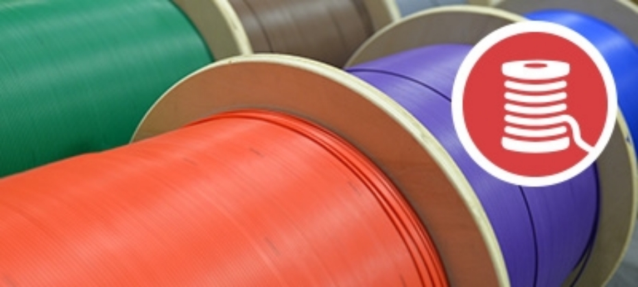


With wireless networks dominating in both homes and businesses it's important to remember that wired networks can boost speeds to those actually promised by ISPs. Especially in the case of businesses having wired networks can lead to a large amount of incoming cables, one way to manage this properly is through the use of Patch Panels. Patch Panels help to centralize your cables making it far easier to work with and manage.

Types of Patch Panels
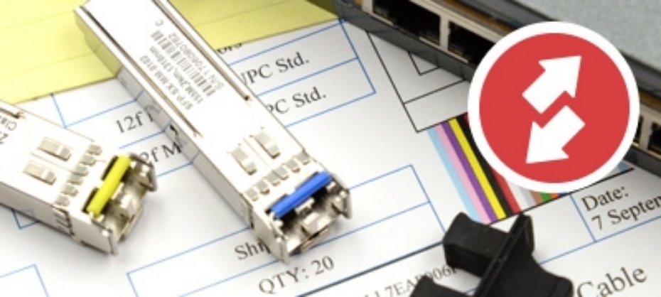
There are various types of copper and fiber patch panels available on the market. In this article we will be dealing primarily with copper patch panels which are designed for both shielded and unshielded copper cables such as the Cat5e, Cat6, Cat6a and Cat7. We with focus on the Cat5e.
Cat5e Patch Cables
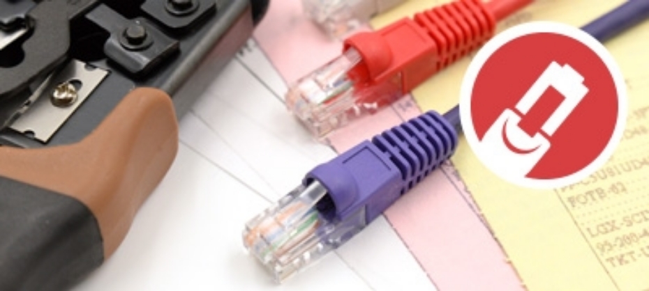
Cat5e is simply put a basic copper Ethernet cable that is used to connect various devices. It is highly recommended that when connecting devices to a patch panel using Cat5e that use a good quality copper cable in either of its two basic types, booted or non-booted. Booted refers to the covering between the end connector and the cable itself. Non-booted cables are mostly only used when the cables with not be frequently unplugged. Check out the cables available from Fibertronics.
Cat5e Patch Panels
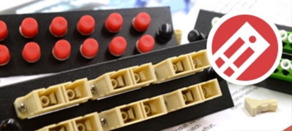
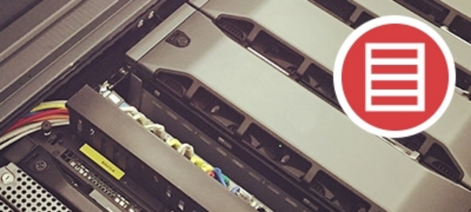
Copper patch panels used in a local area network (LAN) are mounted assemblies that have multiple ports in order to manage Ethernet cables. Patch panels are used to maximise network performance and help with network expansion and growth.
Patch panels are usually divided into 2 catagories, Shielded and Unshielded. Shielded Cat5e patch panels are designed for use in environments with high Electro Magnetic Interference (EMI) which can be caused by the presense of high power electrical cables. Unshielded patch panels are generally used when there is little to no EMI present.
In addition to these differences they can also be found in either Punch-down or Feedthrough configurations. In the case of a punch-down configuration the copper cables are connected to the the numbered RJ45 ports on the front plate. In the rear there are color-coded labels that are either designed for T568A and T568B wiring configurations that the connected cables are punched down into. Learn more about punching down by checking out the video below.
The feedthrough patch panels allow the cables to be connected to the RJ45 ports on the front plate and in the rear without the need to punch them down into the ports. This makes them great for high-density networks where addaptability is important.
Be sure to check out the Fibertronics Ethernet Patch Panels including Cat6 and Cat5e with full premium copper UTP, IDC, Krone, 110 RJ45 and 568 A/B compatibility

 Standalone Media Converte
 Industrial Media Converters
 Chassis-based Media Converters
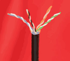 To start off with you will want to begin with preparing the cat cables you intend to punch into the patch panels. You with do so by removing the outer jacket with the cable stripper. If you do not have a cable stripper handy it can also be done with a sharp knife, but please be careful as this method result in both injury to yourself and damage to the inner copper cables.
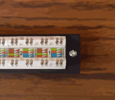 In most cases full patch panels are made up various parts. That being said, it can prove very useful in most situations to break apart the patch panel into it’s small components. This allows for you to work with only the required parts of the panel and makes the entire project simpler to handle on the whole.
 In order to correctly insert the Cat cable wires into the patch panel you will need to take a close look at the color code that is printed on the label adhered to the panel.Let’s take a closer look.
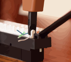 First off you will notice that there are in fact 2 pin-out types, these are typically labelled A and B respectively. Generally most installations would use pin-out B, but please be sure to check which one is right for your specific application.
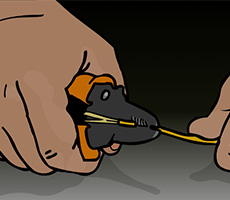 It sounds simple enough right? Unfortunately this is not quite as simple as stripping the simple coating of your average house-hold copper cable. In this case you will first be removing the polymer coating by making use of
 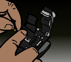 Keeping the fibers clean is of the utmost importance when it comes to fusion splicing. It cannot be repeated enough, ensure that the fibers you are working with are cleaned after every major interaction with them. You do this by gently wiping them down with Alcohol Wipes.
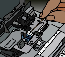 It is now time to make use of your