
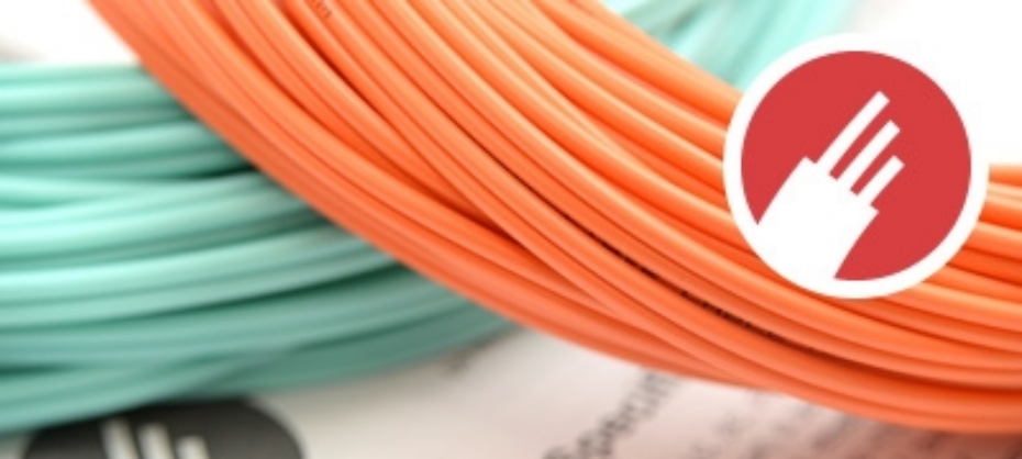
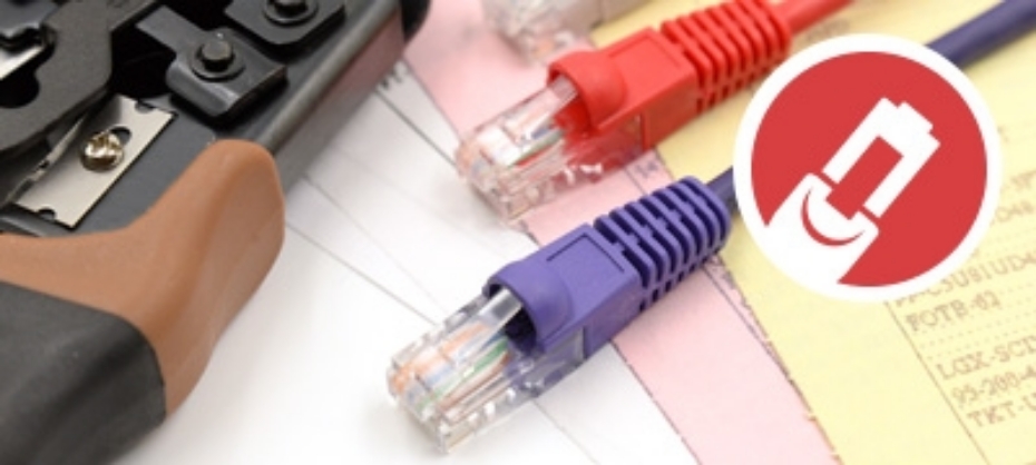

Traditional copper UTP/STP (Unshielded Twisted Pair/Shielded Twisted Pair) Ethernet cables are limited to 100 meters in length. To get around this and extend network connections we have Ethernet Media Converters.

What is a Media Converter?
As mentioned above, Ethernet Media Converters can be used to extend the distance between two network devices that use traditional copper cabling. They can also be used to convert electrical data signals into light pulses which can then be transmitted over fiber optic cables, thus further extending the range. Think of them as a bridge between copper network cables and fiber optic network cables.
Media Converters are able isolate both network nodes from each other and eliminate and ground loops or voltage spikes. This can be extremely useful when it comes to security as it makes in nearly impossible for anyone to tap into a line without detection.
Types of Media Converters
There are essentially 3 categories for media converters. These include Standalone Media Converters, DIN Rail Mount Industrial Converters and Chassis-based Media Converters.
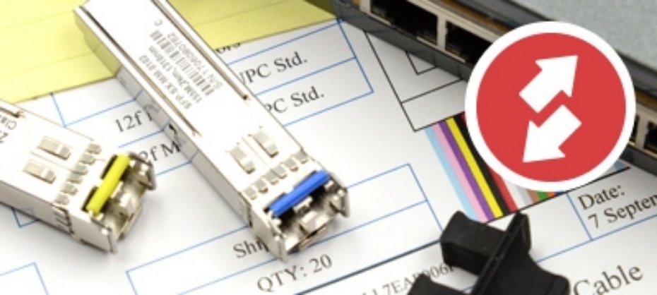
 Standalone Media Converte
Standalone converters are mostly used when only one or two conversions are needed in a network. Converting copper Ethernet into fiber, they support ultra-fast long-distance connections. Aside from extending a network they can also be great at saving both costs and space due to being standalone units as opposed to purchasing an entire chassis. Being small, they conveniently fit where needed making them suitable for environments such as telecoms cabinets or distribution boxes. This coupled with their plug-and-play design makes them an excellent choice.
 Industrial Media Converters
Industrial Media Converters are designed for more heavy duty use in bigger applications. They are able to convert copper Ethernet from Single-mode to Multimode and Multimode to Multimode. Ideal for use in extending the distances of IP camera and wireless access points that can be found in things such as traffic management, oil and gas pipelines, weather tracking and industrial outdoor applications. The use very little power with low heat output all while offering great reliability and stability
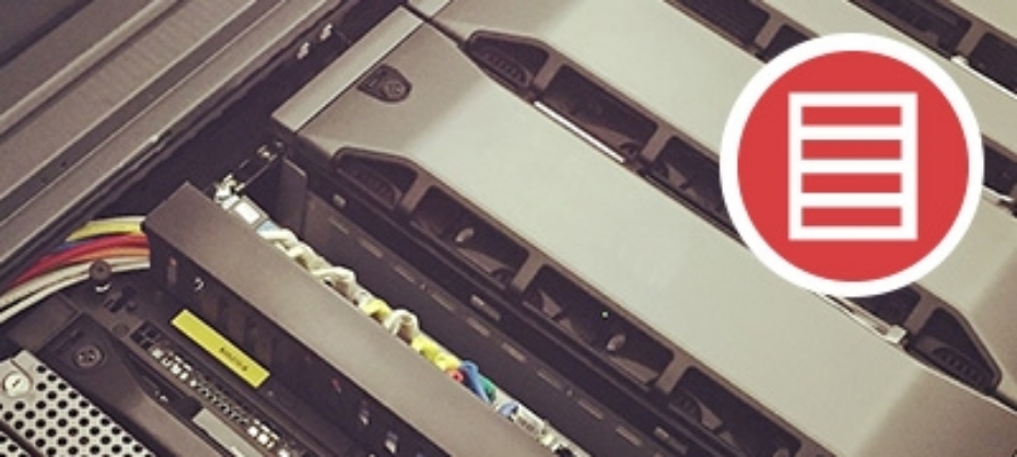
 Chassis-based Media Converters
Chassis-based Media Converters include a number of independent media converters on a chassis capable of holding up to 16 Media Converters. Think of them as a group of individual Media Converters, capable of longer signal transmission between multiple devices. All Media Converters in the system have their own casing and LED indicators with AC to DC power adapters. They themselves are hot-swappable making updating and replacement easy.
The individual Media Converters can be configured as either Managed or Unmanaged.
- Managed is extremely helpful in monitoring the statuses of all the Media Converters and power supplies within the chassis. This is achieved through the use of a Management Module that is available for installation into the chassis. The management follows industry standards, including SNMP (simple network management protocol) and HTTP, which allows monitoring from a third-party SNMP management workstation or via a web browser.
- Unmanaged makes it relatively easy when it comes to installation, however this can lead to problems later on as troubleshooting multiple Media Converters can be both time consuming and difficult.
Quick Summary
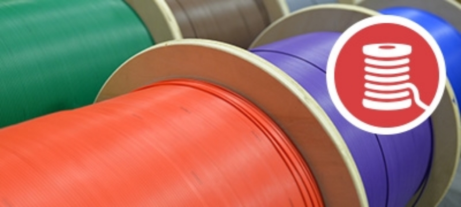
Media Converters allow for seamless integration between different network cable solutions. They support 10Mbps, 10/100Mbps, 100Mbps, 10/100/1000Mbps, Gigabit and 10 Gigabit.
Check out Fibertronics' range of Media Converters to find a solution that works for you, or call us on (321) 473 8933.


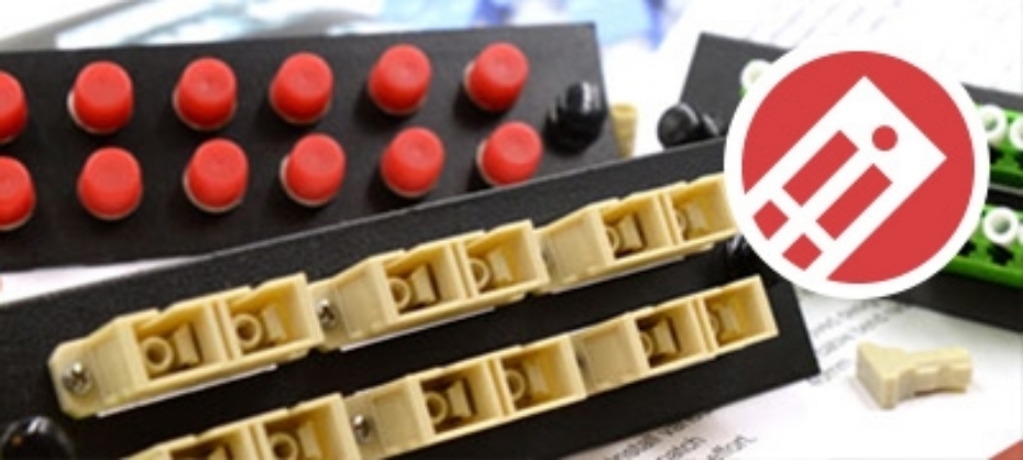
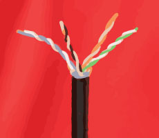 To start off with you will want to begin with preparing the cat cables you intend to punch into the patch panels. You with do so by removing the outer jacket with the cable stripper. If you do not have a cable stripper handy it can also be done with a sharp knife, but please be careful as this method result in both injury to yourself and damage to the inner copper cables.
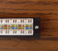 In most cases full patch panels are made up various parts. That being said, it can prove very useful in most situations to break apart the patch panel into it’s small components. This allows for you to work with only the required parts of the panel and makes the entire project simpler to handle on the whole.
 In order to correctly insert the Cat cable wires into the patch panel you will need to take a close look at the color code that is printed on the label adhered to the panel.Let’s take a closer look.
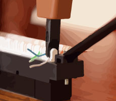 First off you will notice that there are in fact 2 pin-out types, these are typically labelled A and B respectively. Generally most installations would use pin-out B, but please be sure to check which one is right for your specific application.


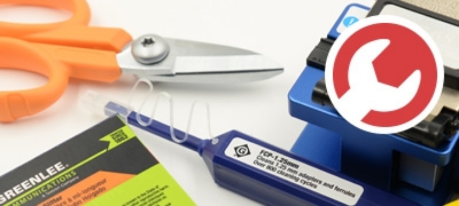
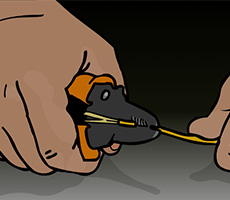 It sounds simple enough right? Unfortunately this is not quite as simple as stripping the simple coating of your average house-hold copper cable. In this case you will first be removing the polymer coating by making use of
 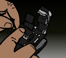 Keeping the fibers clean is of the utmost importance when it comes to fusion splicing. It cannot be repeated enough, ensure that the fibers you are working with are cleaned after every major interaction with them. You do this by gently wiping them down with Alcohol Wipes.
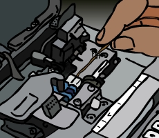 It is now time to make use of your


