

Punching-down a cat cable into a patch panel may seem like tricky business, but once you’ve got the basics down it becomes as easy as the proverbial pie. This high-level guide is here to help.

What You'll Need
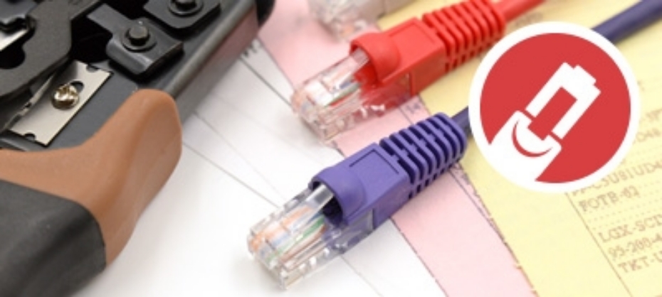
- CAT Cables (Ethernet Cable)
- Patch Panels
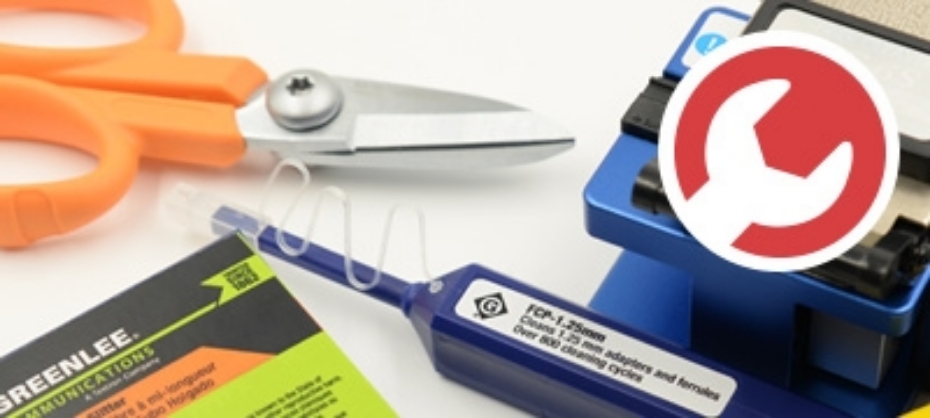
- Punch Down Tool
- Cable Strippers
- Screw Driver
Step 1: Prepare the Cat Cable
 To start off with you will want to begin with preparing the cat cables you intend to punch into the patch panels. You with do so by removing the outer jacket with the cable stripper. If you do not have a cable stripper handy it can also be done with a sharp knife, but please be careful as this method result in both injury to yourself and damage to the inner copper cables.
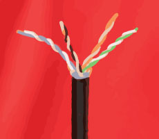
Ideally you should remove approximately 1 inch (25mm) of the outer jacket, this ensures a nice clean fit into the patch panel without the risk of exposing too much cable and damaging it. Once the outer jacket has been removed you will notice 4 pairs of copper cables, making up a total of 8 cables. In order to successfully punch down the cables into the patch panel you will need to gently untwist the pairs so that the 8 cables can be individually worked work with.
Step 2: Prepare the Patch Panel
 In most cases full patch panels are made up various parts. That being said, it can prove very useful in most situations to break apart the patch panel into it’s small components. This allows for you to work with only the required parts of the panel and makes the entire project simpler to handle on the whole.
Take the screwdriver and begin by unscrewing the section of the panel you are going to work with and place the remainder to the side. While doing so take note of the label on the inside of the panel with the color code printed on to it. This will be explained in the next step
Step 3: Put Cat Cable into Patch Panel
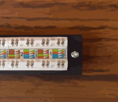
 In order to correctly insert the Cat cable wires into the patch panel you will need to take a close look at the color code that is printed on the label adhered to the panel.Let’s take a closer look.
First off you will notice that there are in fact 2 pin-out types, these are typically labelled A and B respectively. Generally most installations would use pin-out B, but please be sure to check which one is right for your specific application.
Once you have selected a pin-out type you will see that each one has it’s own color code, with 4 solid colors and 4 stripes. Simply match the solid colored wires to the solid color slots and do the same with the stripes. Inserting the wires into the slots requires nothing more than gently pushing them in. Once all the wires have been correctly inserted it is time to being with the actual punching down.
Step 4: Punching Down
 First off you will notice that there are in fact 2 pin-out types, these are typically labelled A and B respectively. Generally most installations would use pin-out B, but please be sure to check which one is right for your specific application.
Once you have selected a pin-out type you will see that each one has it’s own color code, with 4 solid colors and 4 stripes. Simply match the solid colored wires to the solid color slots and do the same with the stripes. Inserting the wires into the slots requires nothing more than gently pushing them in. Once all the wires have been correctly inserted it is time to being with the actual punching down.
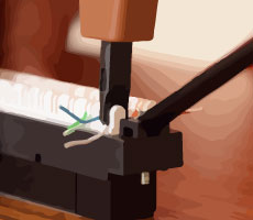
In order to correctly punch down the wires into the patch panel you will need to make use of a Punch Down Tool. The tool itself is fairly simple in that it has a pointed side and a flat size. The pointed side is the side that will trim the ends of the wires to leave a clean cut.
Begin by positioning the tool over the wire you intend to punch down and then using as much force as required push down on the handle of the tool. This will both push the wire firmly into place and trim the ends at the same time., continue doing this for all the remaining wires. You may also notice that occasionally some of the wire ends remain, you can usually fix this by gently removing them by hand as the tool may not have cleaved all the way through the wires on the initial punch down.
Want to watch it? Check out the video below for a short tutorial which outlines most of what we have discussed in this guide.